2. Installation Guidelines
2.1 Mounting and other Mechanical Instructions
2.1.1 Mechanical Characteristics
2.1.2 Mounting instructions
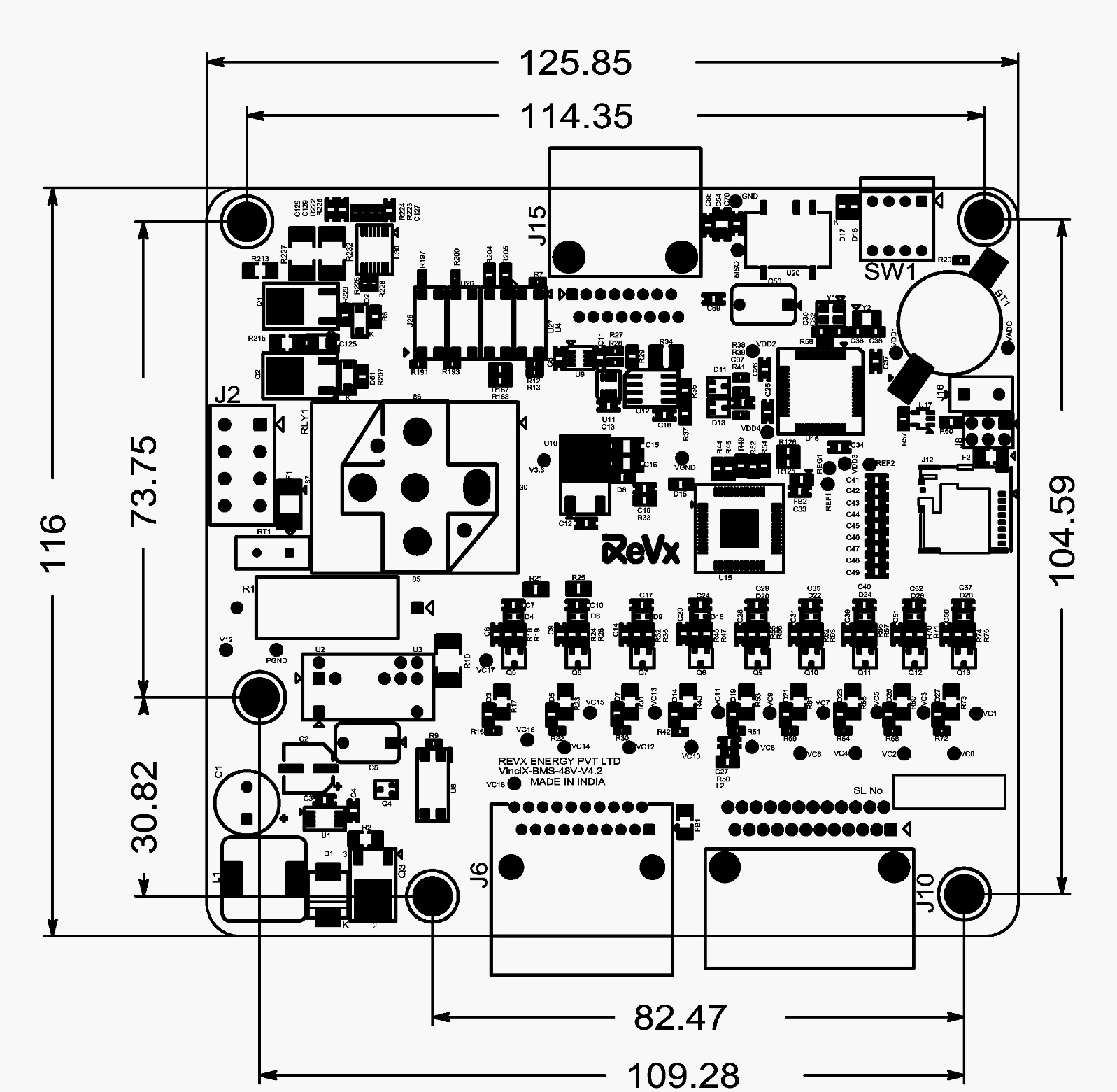
The VinciX-48V-BMS Module is supplied as an assembled Printed Circuit Board (PCB) without any enclosure. To maintain safe operating conditions, it is recommended to mount the PCB in an enclosed metal enclosure and leave approximately 10mm space between the PCB and the metal enclosure on both the top and bottom sides. The board outline drawing is shown in the figure below. There are 5 mounting holes of 4.3mm diameter, and the use of M3 screws to install the board is mandatory.
LVBMS Electrical Installation Instructions
2.2.1 Electrical Connection Overview
2.2.2 Precautions
2.2.3 Cell Voltage Connections
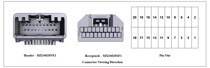
2.2.3.1 Cell Voltage Connector Data
| SL | Particulars | Details |
|---|---|---|
| 1 | MX34020NF1 | Connector Header Through Hole, Right Angle 20 position 0.087" (2.20mm) |
| 2 | MX34020SF1 | 20 Rectangular Connectors - Housings Receptacle Gray 0.087" (2.20mm) |
| 3 | M34S75C4F2 | Crimp terminals, 3A, for cables - AVSS 0.5mm2 , CHFUS 0.5 to 0.75mm2 , CAVS 0.5mm2 , CHFS 0.75mm2 |
| 4 | Manufacturer | JAE Electronics |
| 5 | No of Circuits | 20 |
2.2.3.2 Cell Voltage Connector Pin Out Explanation
| Pin No | Net Name | Description | Connection to Device |
|---|---|---|---|
| 1 | E | Empty | No connection |
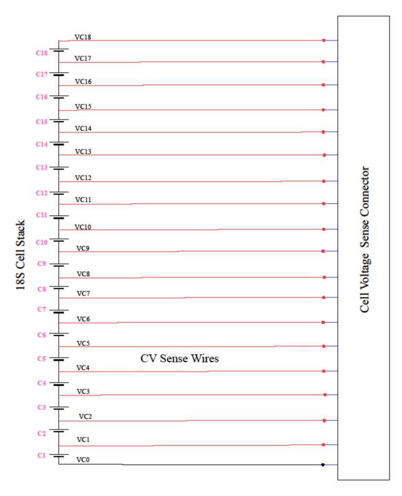
| 2 | VC0 | Negative terminal of the bottom most cell. ( the most negative terminal of the pack, cell 1 negative terminal) | Connect to negative terminal of the Cell 1 of the stack, (the negative terminal of bottom most cell) |
| 3 | VC1 | Cell 1 Voltage Sense | Connect to Cell 1 Positive terminal |
| 4 | VC2 | Cell 2 Voltage Sense | Connect to Cell 2 Positive terminal |
| 5 | VC3 | Cell 3 Voltage Sense | Connect to Cell 3 Positive terminal |
| 6 | VC4 | Cell 4 Voltage Sense | Connect to Cell 4 Positive terminal |
| 7 | VC5 | Cell 5 Voltage Sense | Connect to Cell 5 Positive terminal |
| 8 | VC6 | Cell 6 Voltage Sense | Connect to Cell 6 Positive terminal |
| 9 | VC7 | Cell 7 Voltage Sense | Connect to Cell 7 Positive terminal |
| 10 | VC8 | Cell 8 Voltage Sense | Connect to Cell 8 Positive terminal |
| 11 | VC9 | Cell 9 Voltage Sense | Connect to Cell 9 Positive terminal |
| 12 | VC10 | Cell 10 Voltage Sense | Connect to Cell 10 Positive terminal |
| 13 | VC11 | Cell 11 Voltage Sense | Connect to Cell 11 Positive terminal |
| 14 | VC12 | Cell 12 Voltage Sense | Connect to Cell 12 Positive terminal |
| 15 | VC13 | Cell 13 Voltage Sense | Connect to Cell 13 Positive terminal |
| 16 | VC14 | Cell 14 Voltage Sense | Connect to Cell 14 Positive terminal |
| 17 | VC15 | Cell 15 Voltage Sense | Connect to Cell 15 Positive terminal |
| 18 | VC16 | Cell 16 Voltage Sense | Connect to Cell 16 Positive terminal |
| 19 | VC17 | Cell 17 Voltage Sense | Connect to Cell 17 Positive terminal |
| 20 | VC18 | Cell 18 Voltage Sense | Connect to Cell 18 Positive terminal |
2.2.3.3 Cell Voltage Connection tapping diagram for 18S
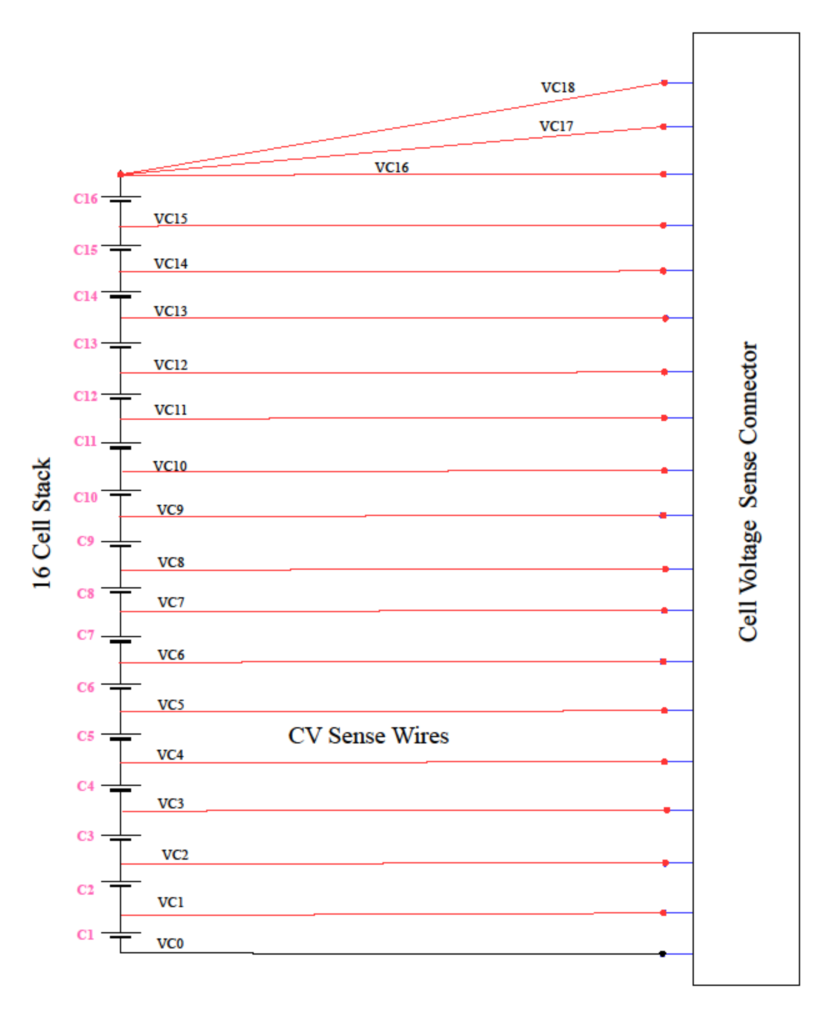
2.2.3.4 Cell Voltage Connection tapping diagram for less than 18S
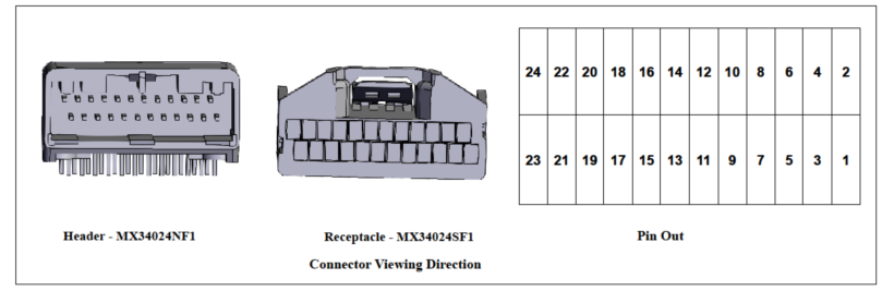
| SL | Particulars | Details |
|---|---|---|
| 1 | MX34024NF1 | Connector Header Through Hole, Right Angle 24 position 0.087" (2.20mm) |
| 2 | MX34024SF1 | 24 Rectangular Connectors - Housings Receptacle Gray 0.087" (2.20mm) |
| 3 | M34S75C4F2 | Crimp terminals, 3A, for cables - AVSS 0.5mm 2 , CHFUS 0.5 to 0.75mm 2 , CAVS 0.5mm 2 , CHFS 0.75mm 2 |
| 4 | Manufacturer | JAE Electronics |
| 5 | No of circuits | 24 |
| 6 | Thermistor Part | TANR-A2E-103R1BD-L101 |
| 7 | Thermistor Manufacturer | Thermosen Technologies |
| 8 | Thermistor Resistance at 25C | 10K |
| 9 | MAXI MUM RATED POWER | 60mW |
| 10 | Thermistor Current @ 25C | 150uA |
| 11 | Mounting Lug Type | NICKLE PLATED BRASS EYELET M6 |
| Pin | Net Name | Description | Connection to Device |
|---|---|---|---|
| 1 | E | Empty | No Connection |
| 2 | E | Empty | No Connection |
| 3 | T1 | External Thermistor1 Input | Connect to 10 kΩ NTC Thermistor Terminal 1 |
| 4 | T1G | External Thermistor1 reference | Connect to 10 kΩ NTC Thermistor Terminal 2 |
| 5 | T2 | External Thermistor2 Input | Connect to 10 kΩ NTC Thermistor Terminal 1 |
| 6 | T2G | External Thermistor2 reference | Connect to 10 kΩ NTC Thermistor Terminal 2 |
| 7 | T3 | External Thermistor3 Input | Connect to 10 kΩ NTC Thermistor Terminal 1 |
| 8 | T3G | External Thermistor3 reference | Connect to 10 kΩ NTC Thermistor Terminal 2 |
| 9 | T4 | External Thermistor4 Input | Connect to 10 kΩ NTC Thermistor Terminal 1 |
| 10 | T4G | External Thermistor4 reference | Connect to 10 kΩ NTC Thermistor Terminal 2 |
| 11 | T5 | External Thermistor5 Input | Connect to 10 kΩ NTC Thermistor Terminal 1 |
| 12 | T5G | External Thermistor5 reference | Connect to 10 kΩ NTC Thermistor Terminal 2 |
| 13 | E | Empty | No connection |
| 14 | E | Empty | No connection |
| 15 | T6 | External Thermistor6 Input | Connect to 10 kΩ NTC Thermistor Terminal 1 |
| 16 | T6G | External Thermistor6 reference | Connect to 10 kΩ NTC Thermistor Terminal 2 |
| 17 | T7 | External Thermistor7 Input | Connect to 10 kΩ NTC Thermistor Terminal 1 |
| 18 | T7G | External Thermistor7 reference | Connect to 10 kΩ NTC Thermistor Terminal 2 |
| 19 | T8 | External Thermistor8 Input | Connect to 10 kΩ NTC Thermistor Terminal 1 |
| 20 | T8G | External Thermistor8 reference | Connect to 10 kΩ NTC Thermistor Terminal 2 |
| 21 | T9 | External Thermistor9 Input | Connect to 10 kΩ NTC Thermistor Terminal 1 |
| 22 | T9G | External Thermistor9 reference | Connect to 10 kΩ NTC Thermistor Terminal 2 |
| 23 | E | Empty | No Connection |
| 24 | E | Empty | No Connection |
| SL | Particulars | Details |
|---|---|---|
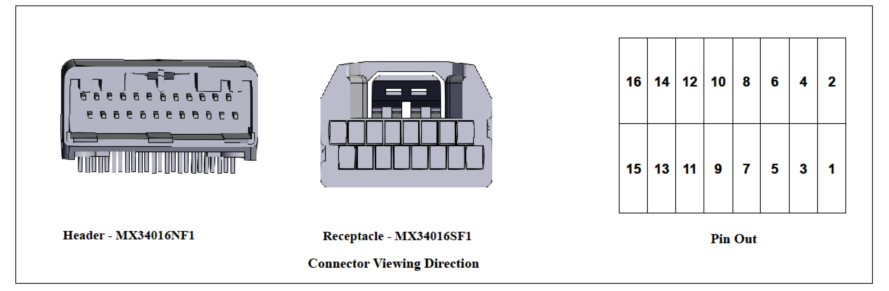
| 1 | MX34016NF1 | Connector Header Through Hole, Right Angle 16 position 0.087" (2.20mm) |
| 2 | MX34016SF1 | 16 Rectangular Connectors - Housings Receptacle Gray 0.087" (2.20mm) |
| 3 | M34S75C4F2 | Crimp terminals, 3A, for cables - AVSS 0.5mm2 , CHFUS 0.5 to 0.75mm2 , CAVS 0.5mm2 , CHFS 0.75mm2 |
| 4 | Manufacturer | JAE Electronics |
| 5 | No of Circuits | 16 |
| Pin | Net Name | Description | Connection to Device |
|---|---|---|---|
| 1 | GPIO 1 | Potential Free General Purpose IO1 + | |
| 2 | +12V | 12V Control Supply for GPIOs | |
| 3 | GPIO 1 RTN | Potential Free General Purpose IO1 Return | |
| 4 | GPIO O/P 1 | 12V Level GPIO Output 1 | |
| 5 | 12V GND | 12V Control Ground for GPIOs | |
| 6 | FAN OP | Thermal ON or FAN enable 12V GPIO O/P, current limited to 5 mA | Connect to FAN Enable input |
| 7 | IGN | +12V Level Ignition loopback Input, current limited to 5mA | Connect to Vehicle Ignition Key and return ack to the 12V GND |
| 8 | CGND | Control Ground | |
| 9 | DD Protect | Deep Discharge Protection Switch | Connect to Panel mount deep discharge protection switch and return back to 12V GND |
| 10 | 11 | Shunt Sense Connection 1 | Connect to shunt sense connection – towards battery side |
| 11 | ISO_GND | Isolated Ground for CAN | |
| 12 | 12 | Shunt Sense Connection 2 | Connect to shunt sense connection – towards Load side |
| 13 | CAN H | CAN Communication High | Connect to CAN H bus of the Can Network |
| 14 | CGND | Control Ground for Hall Sensor | No connection |
| 15 | CAN H | CAN Communication Low | Connect to CAN L bus of the Can Network |
| 16 | +5V | 5V Power for Hall sensor | Connect to +5V Power pin of the hall sensor |