2. Functional and Safety Tests
2.1. Cell Voltage Measurement
| Operational Mode | Operating mode 2.2 | ||||||||||||||||||||||||||||||||||||||||||||||||||||||||||||
| Test objective | DUT detecting cell temperature over complete measurement range | ||||||||||||||||||||||||||||||||||||||||||||||||||||||||||||
| Test Definition |
|
||||||||||||||||||||||||||||||||||||||||||||||||||||||||||||
| Monitored Signals |
| ||||||||||||||||||||||||||||||||||||||||||||||||||||||||||||
| Test Criteria | - DUT shall be able to measure cell voltages with +/- 5mv accuracy | ||||||||||||||||||||||||||||||||||||||||||||||||||||||||||||
| Test Results |
- DUT is able to measure cell voltages over complete measurement range with +/- 5mV accuracy.
|
2.2. Cell Temperature Measurement
| Operational Mode | Operating mode 2.2 | ||||||||||||||||||||||||||||||||||||||||
| Test objective | DUT detecting cell voltages over complete measurement range | ||||||||||||||||||||||||||||||||||||||||
| Test Definition |
|
||||||||||||||||||||||||||||||||||||||||
| Monitored Signals | All Cell Temperature should be recorded | ||||||||||||||||||||||||||||||||||||||||
| Test Criteria | - DUT shall be able to measure cell voltages with +/- 1C accuracy | ||||||||||||||||||||||||||||||||||||||||
| Test Results |
- DUT is able to measure cell voltages over complete measurement range with +/- 1C accuracy.
Expected Temperature at 2kohms: 66.12675 Measured Temperature at 2kohms: 66.598 |
2.3. Battery and Load Voltage Measurement
| Operational Mode | Operating mode 2.2 | ||||||||||||||||
| Test objective | DUT detecting pack voltage, battery voltage and load voltage in rest mode | ||||||||||||||||
| Test Definition |
|
||||||||||||||||
| Monitored Signals | - Pack Voltage, Battery Voltage and Load Voltage | ||||||||||||||||
| Test Criteria | - DUT shall be able to measure cell voltages with +/- 1V accuracy | ||||||||||||||||
| Test Results |
- DUT is able to measure voltages over complete measurement range with +/- 1V accuracy.
|
2.4. Charge and Discharge Current Measurement
| Operational Mode | Operating mode 2.2 | |||||||||||||||||||||||||||||||||||||||
| Test objective | DUT detecting charge and discharge current | |||||||||||||||||||||||||||||||||||||||
| Test Definition |
|
|||||||||||||||||||||||||||||||||||||||
| Monitored Signals | - Discharge Current and Charge Current | |||||||||||||||||||||||||||||||||||||||
| Test Criteria | - DUT shall be able to measure current with +/- 1A accuracy | |||||||||||||||||||||||||||||||||||||||
| Test Results |
- DUT is able to measure current over complete measurement range with +/- 1A accuracy. Charge Current:
Discharge Current
|
2.5. SD Card
| Operational Mode | Operating mode 2.2 | |||||||||||||||||||||||||||||||||||||||||||||||||||||||||||||||||||||||||||||||||||||||||||||||||||||||||||||||||||||||||||||||||
| Test objective | BMS writing logs and events in sd card | |||||||||||||||||||||||||||||||||||||||||||||||||||||||||||||||||||||||||||||||||||||||||||||||||||||||||||||||||||||||||||||||||
| Test Definition |
|
|||||||||||||||||||||||||||||||||||||||||||||||||||||||||||||||||||||||||||||||||||||||||||||||||||||||||||||||||||||||||||||||||
| Monitored Signals | - Logs and Event file | |||||||||||||||||||||||||||||||||||||||||||||||||||||||||||||||||||||||||||||||||||||||||||||||||||||||||||||||||||||||||||||||||
| Test Criteria | - GUI shall be able to read logs and event from DUT sd card | |||||||||||||||||||||||||||||||||||||||||||||||||||||||||||||||||||||||||||||||||||||||||||||||||||||||||||||||||||||||||||||||||
| Test Results |
GUI is able to read logs and event file from DUT sd card Snapshot of log file - All Cell voltages, Cell temperature, Pack voltage, Pack Curren, BMS State, SOC, SOH are recorded in SD Card in every 10sec interval - Every day new csv file is created to keep logs
Snapshot of Event file - All BMS state machine events are recorded in event file - Every day new csv file is created to keep events
|
2.6. CAN and RS485 Communication
| Operational Mode | Operating mode 2.2 |
|---|---|
| Test objective | BMS communicating over CAN and RS485 |
| Test Definition | 1. DUT shall be in operating mode 2.2 2. GUI is connected to DUT over RS485 3. DUT CAN is connected to system PCAN 4. Check if GUI is getting parameter from DUT in scan mode 5. Check if PCAN is getting CAN parameter from DUT as per CAN DBC |
| Monitored Signals | GUI Parameters and PCAN trace |
| Test Criteria | - GUI shall be able to communicate over RS485 and CAN |
| Test Results | - DUT is able to communicate over RS485 and CAN GUI Screenshot: 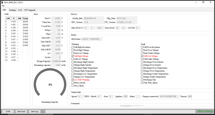 PCAN Screenshot: 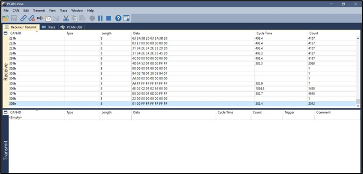 |
2.7. State Machine
| Operational Mode | Operating mode 2.2 | ||||||||||||||||||||||||||||||||||||||||||||||||||||||||||||||||||||||||||||||||||||||||||||||||||||
| Test objective | DUT states and state transition | ||||||||||||||||||||||||||||||||||||||||||||||||||||||||||||||||||||||||||||||||||||||||||||||||||||
| Test Definition |
|
||||||||||||||||||||||||||||||||||||||||||||||||||||||||||||||||||||||||||||||||||||||||||||||||||||
| Monitored Signals | - DUT State on GUI | ||||||||||||||||||||||||||||||||||||||||||||||||||||||||||||||||||||||||||||||||||||||||||||||||||||
| Test Criteria | - DUT shall be able to make all state transition | ||||||||||||||||||||||||||||||||||||||||||||||||||||||||||||||||||||||||||||||||||||||||||||||||||||
| Test Results |
- DUT is able to make all state transition
|
2.8. Cell High Voltage Warning and Cell Over Voltage Fault
| Operational Mode | Operating mode 2.2 |
| Test objective | DUT detecting cell high voltage warning and cell over voltage fault for single cell or multiple cells and taking protective measures |
| Test Definition |
|
| Monitored Signals |
|
| Test Criteria |
- DUT shall be able to detect cell high voltage warning, cell over voltage fault and prohibit further charging - Load Contactor should open - After Disconnecting charger and turning on ignition warning and fault shall reset and contactor should turn on |
| Test Results |
- DUT is able to detect cell high voltage warning and cell over voltage fault within configured time - DUT is able to reset warning and fault after ignition is turned on and charger is disconnected |
2.9. Pack High Voltage Warning and Pack Over Voltage Fault
| Operational Mode | Operating mode 2.2 |
| Test objective | DUT detecting pack high voltage warning and pack over voltage fault and taking protective measures |
| Test Definition |
|
| Monitored Signals |
|
| Test Criteria |
- DUT shall be able to detect pack high voltage warning, pack over voltage fault and prohibit further charging - Load Contactor should open - After Disconnecting charger and turning on ignition warning and fault shall reset and contactor should turn on |
| Test Results |
- DUT is able to detect pack high voltage warning and pack over voltage fault within configured time - DUT is able to reset warning and fault after ignition is turned on and charger is disconnected |
2.10. Cell Low voltage warning and Cell Under voltage fault
| Operational Mode | Operating mode 2.2 |
| Test objective | DUT detecting cell low voltage warning and cell under voltage fault for single cell or multiple cells and taking protective measures |
| Test Definition |
|
| Monitored Signals |
|
| Test Criteria |
- DUT shall be able to detect cell low voltage warning, cell under voltage fault and prohibit further discharge - Load Contactor should open - After Disconnecting load, turning off ignition and turning on charger warning and fault shall reset and contactor should turn on |
| Test Results |
- DUT is able to detect cell low voltage warning and cell under voltage fault within configured time - DUT is able to reset warning and fault after ignition is turned off and charger is connected |
2.11. Pack Low Voltage Warning and Pack Under Voltage Fault
| Operational Mode | Operating mode 2.2 |
| Test objective | DUT detecting pack low voltage warning and pack under voltage fault and taking protective measures |
| Test Definition |
|
| Monitored Signals |
|
| Test Criteria |
- DUT shall be able to detect pack low voltage warning, pack under voltage fault and prohibit further discharge - Load Contactor should open - After Disconnecting load, turning off ignition and turning on charger warning and fault shall reset and contactor should turn on |
| Test Results |
- DUT is able to detect pack low voltage warning and pack under voltage fault within configured time - DUT is able to reset warning and fault after ignition is turned off and charger is connected |
2.12. Charge and Discharge High Current Warning and Over Current Fault
| Operational Mode | Operating mode 2.2 |
| Test objective | DUT detecting high current warning and over current fault in charge and discharge state and taking protective measures |
| Test Definition |
|
| Monitored Signals |
|
| Test Criteria |
- DUT shall be able to detect Discharge High current warning, Discharge over current fault and prohibit further discharge - Load Contactor should open - After Disconnecting load, turning off ignition and turning on charger warning and fault shall reset and contactor should turn on - DUT shall be able to detect Charge high current warning, Discharge over current Fault and prohibit further charge - Load Contactor should open - After disconnecting charger, turning on ignition warning and fault shall reset and contactor |
| Test Results |
- DUT is able to detect Discharge High Current warning and over current fault within configured time - DUT is able to reset warning and fault after ignition is turned off and charger is connected - DUT is able to detect Charge High Current warning and over current fault within configured time - DUT is able to reset warning and fault after charger is turned off and Ignition is turned on |
2.13. Charge and Discharge High Temperature Warning and Over Temperature Fault
| Operational Mode | Operating mode 2.2 |
| Test objective | DUT detecting high temperature warning and over temperature fault in charge and discharge state and taking protective measures |
| Test Definition |
|
| Monitored Signals |
|
| Test Criteria |
- DUT shall be able to detect Discharge High current warning, Discharge over current fault and prohibit further discharge - Load Contactor should open - After decreasing temperature signal warning and fault shall reset and contactor should turn on - DUT shall be able to detect Charge High temperature warning, over temperature Fault and prohibit further charge - Load Contactor should open - After decreasing temperature signal warning and fault shall reset and contactor should turn on |
| Test Results |
- DUT is able to detect Discharge High temperature warning and over temperature fault within configured time - DUT is able to reset warning and fault once temperature is decreased - DUT is able to detect Charge High temperature warning and over temperature fault within configured time - DUT is able to reset warning and fault once temperature is decreased |
2.14. Charge and Discharge Low Temperature Warning and Under Temperature Fault
| Operational Mode | Operating mode 2.2 |
| Test objective | DUT detecting low temperature warning and under temperature fault in charge and discharge state and taking protective measures |
| Test Definition |
|
| Monitored Signals |
|
| Test Criteria |
- DUT shall be able to detect Discharge low current warning, Discharge under current fault and prohibit further discharge - Load Contactor should open - After increasing temperature signal warning and fault shall reset and contactor should turn on - DUT shall be able to detect Charge low temperature warning, over temperature Fault and prohibit further charge - Load Contactor should open - After increasing temperature signal warning and fault shall reset and contactor should turn on |
| Test Results |
- DUT is able to detect Discharge low temperature warning and under temperature fault within configured time - DUT is able to reset warning and fault once temperature is increased - DUT is able to detect Charge low temperature warning and over temperature fault within configured time - DUT is able to reset warning and fault temperature is decreased |
2.15. Fuse Open
| Operational Mode | Operating mode 2.2 |
| Test objective | DUT detecting Fuse open and taking protective measure |
| Test Definition |
|
| Monitored Signals |
|
| Test Criteria |
- DUT shall be able to detect Fuse open and contactor should open |
| Test Results |
- DUT is able to detect Fuse open within configured time |
2.16. Cell Voltage Sensing Open
| Operational Mode | Operating mode 2.2 |
| Test objective | DUT detecting Cell wire open and taking protective measure |
| Test Definition |
|
| Monitored Signals |
|
| Test Criteria |
|
| Test Results |
|
2.17. Cell Temperature Sensing Open
| Operational Mode | Operating mode 2.2 |
| Test objective | DUT detecting thermistor open and taking protective measure |
| Test Definition |
|
| Monitored Signals |
|
| Test Criteria |
|
| Test Results |
|