1. Definition of Test Sample
As Exact configuration of the system in use may differ, smallest functional setup of the BMS is tested. All main feature of BMS during testing is active, this includes:
- Cell Voltage Measurement
- Cell Temperature Measurement
- Pack Voltage Measurement
- Pack Current Measurement
- Communication Channels: CAN, RS485
- Contactor Control
- Logging: SD CARD
1.1. Operating Modes and Test Criteria
Operating Mode 1:
- No Supply voltage, DUT of
1. Operating mode 1.1: No wiring connected
2. Operating mode 1.2: All wiring connected
Operating Mode 2:
- DUT is electrically connected to all sensors and contactors.
1. Operating mode 2.1: DUT functions are not activated
2.
Operating mode 2.2: DUT is active and load is not connected
3.
Operating mode 2.3: DUT is active and load is connected
1.2. Functional Status
Function state of BMS after test is captured, below definitions are derived from ISO 16750-1.
Function state of BMS after test is captured, below definitions are derived from ISO 16750-1.
| A | All functions of the device/system perform as designed during and after the test. | No error messages should occur. The whole system, e.g. temperature and single cell voltage measurement has to work as specified. |
|---|---|---|
| B | All functions of the device/system perform as designed during the test. However, one or more of them may go beyond the specified tolerance. All functions return automatically within normal limits after the test. Memory functions shall remain class A. It shall be specified by the vehicle manufacturer which function of the DUT must perform as designed. | The whole system, e.g. temperature and single cell voltage measurement has to work as specified. Functions from the BMS which are not working in the allowed tolerance should be named by the manufacturer in advance with reason. |
| C | One or more functions of a device/system do not perform as designed during the test but return. | Allowed are short outages of communication or deviations from measurement tolerances due to load. All safety relevant features shall stay functional to be able to react in an appropriate way. |
| D | One or more functions of a device/system do not perform as designed during the test and do not return. | Errors of the BMS which can be reseted by a reboot or internal reset of the fault memory. |
| E | One or more functions of a device/system do not perform as designed during and after the test and cannot be returned to proper operation without repairing or replacing them. | Permanent damage so that some functions are not working anymore, or loose parts occur. |
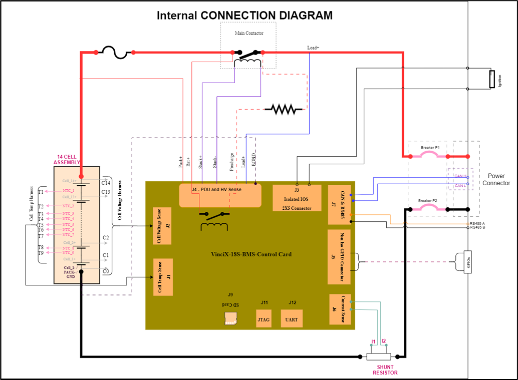
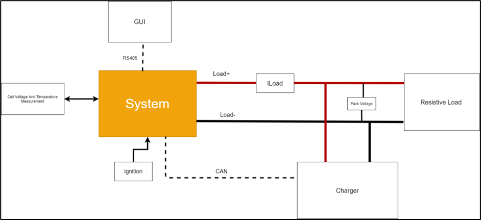
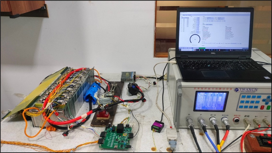
1.3. Test Setup
Test setup is as per below Internal and System Connection Diagram.