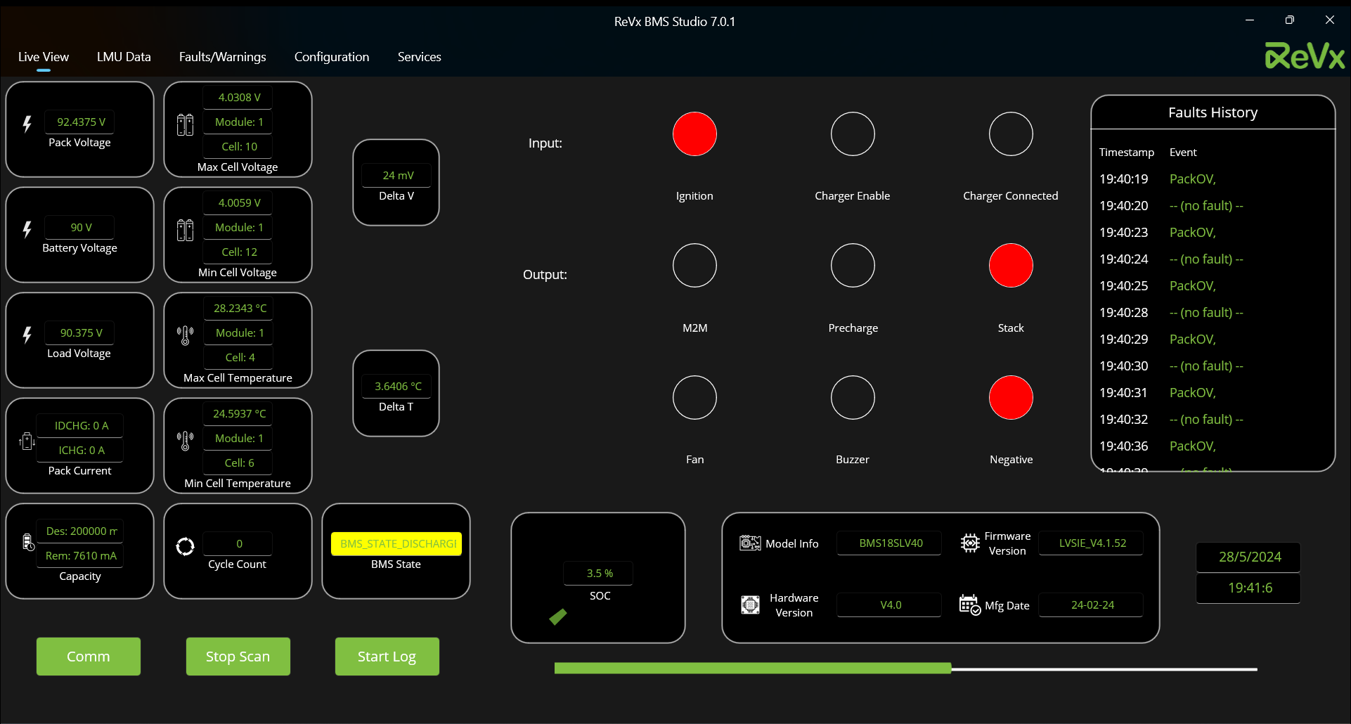
4. Live View
4.1. Parameters
[ Note: In the parameters list below, heading is the full parameter name and the name in brackets next to it is the parameter name in the application. If there is no bracket next to the heading, assume that the heading is the parameter name in the application.]
4.1.1. Pack Voltage
Unit: [ Volts ]
This is the sum of individual cell voltages from AFE [Analog Front End].
Number of cell voltages [Configuration] should be configured properly for proper pack voltage measurment.
4.1.2. Battery Voltage
Unit: [ Volts ]
This is the analog voltage sensed by BMS controller. This is before contactor.
Vgain [Configuration] should be configured properly for proper pack voltage measurment.
4.1.3 Load Voltage
Unit: [ Volts ]
This is the analog voltage sensed by BMS controller. This is after contactor.
Vgain [Configuration] should be configured properly for proper pack voltage measurment.
4.1.4. Pack Current
This parameter has two values namely,
Igain [Configuration] should be configured properly for proper pack voltage measurment.
4.1.4.1. Discharge Current ( IDCHG )
Unit: [ Amperes ]
This is the discharge current measured by BMS via shunt or hall sensor.
4.1.4.2. Charge Current ( ICHG )
Unit: [ Amperes ]
This is the charge current measured by BMS via shunt or hall sensor.
4.1.5. Capacity
This parameter has two values namely,
4.1.5.1. Design Capacity ( Des )
Unit: [ milli Ampere hours ]
This is the full charge capacity of battery pack without considering health of battery.
4.1.5.2. Remaining Capacity ( Rem )
Unit: [ milli Ampere hours ]
This is the current remaining capacity in the battery. This has direct correlation with SOC.
4.1.6. Maximum Cell Voltage ( Max Cell Voltage )
This parameter has three values namely,
4.1.6.1. Maximum Cell Voltage
Unit: [ Volts ]
This is the current measured maximum cell voltage in the battery pack.
4.1.6.2. Module Number ( Module )
Unit: [ NA ]
This is the current measured module number of the maximum voltage cell in the battery pack.
4.1.6.3. Cell Number ( Cell )
Unit: [ NA ]
This is the current measured cell number of the maximum voltage cell in it's module.
4.1.7. Minimum Cell Voltage ( Min Cell Voltage )
This parameter has three values namely,
4.1.7.1. Minimum Cell Voltage
Unit: [ Volts ]
This is the current measured minimum cell voltage in the battery pack.
4.1.7.2. Module Number ( Module )
Unit: [ NA ]
This is the current measured module number of the minimum voltage cell in the battery pack.
4.1.7.3. Cell Number ( Cell )
Unit: [ NA ]
This is the current measured cell number of the minimum voltage cell in it's module.
4.1.8. Maximum Cell Temperature ( Max Cell Temperature )
This parameter has three values namely,
4.1.8.1. Maximum Cell Temperature
Unit: [ °C ]
This is the current measured maximum cell temperature.
4.1.8.2. Module Number ( Module )
Unit: [ NA ]
This is the current measured module number of the maximum temperature thermistor.
4.1.8.3. Cell Number ( Cell )
Unit: [ NA ]
This is the current measured cell number of the maximum temperature thermistor in it's module.
4.1.9. Minimum Cell Temperature ( Min Cell Temperature )
This parameter has three values namely,
4.1.9.1. Minimum Cell Temperature
Unit: [ °C ]
This is the current measured minimum cell temperature.
4.1.9.2. Module Number ( Module )
Unit: [ NA ]
This is the current measured module number of the minimum temperature thermistor.
4.1.9.3. Cell Number ( Cell )
Unit: [ NA ]
This is the current measured cell number of the minimum temperature thermistor in it's module.
4.1.10. Cycle Count
Unit: [ NA ]
This is the current measured total cycle count of the battery pack.
4.1.11. Delta Voltage ( Delta V )
Unit: [ milli Volts ]
This is the current measured difference of maximum and minimum voltages of the maximum and minimum cells in the battery pack respectively.
4.1.11. Delta Temperature ( Delta T )
Unit: [ °C ]
This is the current measured difference of maximum and minumum temperatures maximum and minimum temperature thermistors respectively.
4.1.11. BMS State
Unit: [ NA ]
This is the current measured state of the battery pack.
Color coding:-
4.1.11.1. BMS_STATE_DISCHARGE 
This state is indicated by the background color of container of this parameter turning yellow.
4.1.11.2. BMS_STATE_CAN_CHARGE 
This state is indicated by the background color of container of this parameter turning green.
4.1.11.3. BMS_STATE_FAULT 
This state is indicated by the background color of container of this parameter turning red.
[ Note: All other states have transparent container color. ]
4.1.12. State Of Charge ( SOC )
Unit: [ Percentage ]
This value is the current measured state of charge of the battery pack. This value is indicated in a gauge in a separate section in live view page.
4.1.13. BMS Information
4.1.13.1. Model Information ( Model Info )
4.1.13.1. Model Information ( Model Info )
This value is the model number of the BMS connected to the battery pack.
4.1.13.2. Firmware Version
This value is the firmware version loaded in the BMS connected to the battery pack.
4.1.13.3. Hardware Version
This value is the hardware version of the BMS connected to the battery pack.
4.1.13.4. Manufacture Date ( Mfg Date )
This value is the manufacture date of the BMS connected to the battery pack.
4.1.14. Inputs
The inputs of the bms are as follows:-
4.1.14.1. Ignition
This input is red when ignition is on. Default value is transparent.
Check with ReVx whether Ignition should be 12V input or Self loop. This is depending on hardware version.
4.1.14.2. Charger Enable
This input is red when charger is enabled. Default value is transparent.
4.1.14.3. Charger Connected
This input is red when charger is connected. Default value is transparent.
4.1.15. Output
The output of the bms are as follows:-
4.1.15.1. M2M [Module to Module Contactror]
This output is red when M2M is on. Default value is transparent.
4.1.15.2. Precharge [Precharge Relay/Contactor]
This output is red when Precharge is on. Default value is transparent.
4.1.15.3. Stack [Positive Relay/Contactor]
This output is red when Stack is enabled. Default value is transparent.
4.1.15.4. Fan
This output is red when Fan is on. Default value is transparent.
4.1.15.5. Buzzer
This buzzer is red when Buzzer is on. Default value is transparent.
4.1.15.6. Negative [Negative Relay/Contactor]
This buzzer is red when Negative is on. Default value is transparent.
4.1.16. Date
Format: [ d/M/yyyy ]
This value is the current measured date in the BMS connected to the battery pack. Date is coming via RTC of BMS. This value is the upper value located at the bottom-right of the live-view screen.
4.1.17. Time
Format: [ HH:mm:ss ]
This value is the current measured time in the BMS connected to the battery pack. Time is coming via RTC of BMS. This value is the lower value located at the bottom-right of the live-view screen.
4.2. Faults History
This window is located at the top-right of the live view screen and has two parameters, namely
4.2.1. Timestamp
Format: [ HH:mm:ss ]
This value is the timestamp of the new fault or warning generated in the BMS.
4.2.2. Event
This value is the new fault(s) or warning(s) generated in the BMS in a single comma separated string.
Note the following related to the faults history window:-
- This window shows the faults and warnings in the pack during the current scan session.
- A maximum of 30 entries are shown at once. A FIFO (First-In-First-Out) scheme is followed when entries exceed the maximum amount.
- When you restart the app after closing or navigate to live view page from communication settings page, this window contains the faults generated during the last scan session before closing the app or before navigating to communication settings screen during or after a scan session.